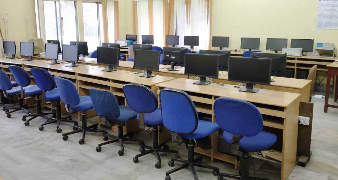
Control System Lab
Space: 110 sq. mtr.
Batch size: 30-35 (1 Computer for 1 student)
Major equipment: Computers and MATLAB software, PID controller, AC servomotor

List of Experiments:
Familiarization with MAT-Lab control system tool box, MAT-Lab- simulink tool box & PSPICE
Determination of Step response for first order & Second order system with unity feedback on CRO & calculation of control system specification like Time constant, % peak overshoot, settling time etc. from the response.
Simulation of Step response & Impulse response for type-0, type-1 & Type-2 system with unity feedback using MATLAB & PSPICE.
Determination of Root locus, Bode plot, Nyquist plot using MATLAB control system tool box for 2nd order system & determination of different control system specification from the plot.
Determination of PI, PD and PID controller action of first order simulated process.
Determination of approximate transfer functions experimentally from Bode plot.
Evaluation of steady state error, setting time , percentage peak overshoot, gain margin, phase margin with addition of Lead.
STUDY OF A PRACTICAL POSITION CONTROL SYSTEM. Obtaining closed step responses for gain setting corresponding to over-damped and under-damped responses. Determination of rise time and peak time using individualized components in SIMULINK. Determination of un-damped natural frequency and damping ratio from the experimental data.
TUNING OF P, PI, AND PID CONTROLLER FOR FIRST ORDER PLANT WITH DEAD TIME USING Z-N METHOD. Process parameters (time constant and delay/lag) will be provided, the students would compute controller gains by using Z-N method. Steady state and transient performance of the closed loop plant with and without steady disturbances will have to be noted. Theoretical phase and gain margins will have to be manually computed for each gain settings.
DESIGN OF LEAD AND LAG COMPENSATION USING CACSAD TOOLS (Plant transfer function will be provided. Step response is to be obtained. (PSPICE, MATLAB, SciLab may be used).
STATE VARIABLE ANALYSIS USING CACSAD COMMAND TOOL. Familiarization and use of CACSAD command for state variable analysis. Obtaining transfer function from SV model and vice versa. Obtaining step response for a SISO system given in SV form. (PSPICE, MATLAB, SciLab may be used).
STATE VARIABLE ANALYSIS USING CACSAD BLOCK DIAGRAM TOOL. Familiarization and use of CACSAD BLOCK DIAGRAM TOOL for state variable analysis. Obtaining step response and initial condition response for a single input, two output system given in SV form (PSPICE, MATLAB, SciLab may be used).
PERFORMANCE ANALYSIS OF A DISCRETE TIME SYSTEM USING CACSAD TOOL. Familiarization and use of CACSAD block diagram tool for Digital Control System. Study of closed response of a continuous system with a digital controller with sample and hold. (PSPICE, MATLAB, SciLab may be used).
STUDYING THE EFFECTS OF NONLINEARITY IN A FEEDBACK CONTROLLED SYSTEM USING TIME RESPONSE. Determination of step response with a limiter nonlinearity introduced into the forward path of 2nd order unity feedback control systems. The open loop plant will have one pole at the origin and the other pole will be in LHP or RHP. To verify that (i) with open loop stable pole, the response is slowed down for larger amplitude input and (ii) for unstable plant , the closed loop system may become oscillatory with large input amplitude. (PSPICE, MATLAB, SciLab may be used).
STUDYING THE EFFECTS OF NONLINEARITY IN A FEEDBACK CONTROLLED SYSTEM USING PHASE PLANE PLOTS. Determination of phase plane trajectory and possibility of limit cycle of common nonlinearities. CACSAD block diagram tool will be used (PSPICE, MATLAB, SciLab may be used).